A useful virtual electricity lesson asks students to predict a change before pressing a preset. Will a non-ideal voltmeter make a resistance reading too high or too low? Why does a transformer need changing flux? What exactly does the induced field oppose?
Start with the Ohm’s law and volt-ampere resistance simulator, then use the transformer and induction labs to connect circuit measurements with changing magnetic fields. This guide follows the public simulator documentation reviewed on 18 November 2026 (Asia/Shanghai). Activities below mix proposed investigations with measurements taken in Light appearance on 18 November 2026 (Asia/Shanghai): the small-resistor external wiring case, the constant-DC transformer preset, and an N-pole approach in the Lenz lab. Preset titles and rounded card figures are not treated as the more precise live metrics.
Investigation 1: why measuring resistance changes the circuit
Question: When calculating R_meas = U_meter/I_meter, are both meters measuring only the unknown resistor?
Use this complete setup for the first comparison:
| Control | Set it to |
|---|---|
| Unknown resistance Rx | 5 Ω |
| Ammeter resistance RA | 0.5 Ω |
| Voltmeter resistance RV | 3000 Ω |
| Circuit type | External wiring / type 1 |
| Animation speed | 1.0× |
Use the small-resistor external-wiring preset if available, but inspect all the resulting controls rather than assuming its label establishes them. Pause when the circuit and derivation are readable.
- Sketch which branch carries voltmeter current. Predict the sign of the resistance error.
- Record the measured resistance, displayed relative error and recommended wiring exactly as shown.
- Keep Rx, RA and RV fixed, switch to internal wiring, then record the same quantities.
- Explain the difference using the meter connections, not “the animation looked faster”.
In the documented external arrangement, the voltmeter is across Rx and the ammeter includes the voltmeter branch current. Thus the inferred resistance is the parallel combination:
R_meas = Rx × RV / (Rx + RV) < Rx
In the internal arrangement, the voltmeter includes the ammeter’s voltage drop while the ammeter measures the Rx branch current:
R_meas = Rx + RA > Rx
These expressions explain systematic loading in this circuit model. They are predictions from the connections, not recorded meter readings. OpenStax’s electrical-instruments discussion explains why ammeters are connected in series, voltmeters in parallel, and their non-ideal resistances matter.
At 07:38:20 Asia/Shanghai on 18 November 2026, in this dynamic simulator (not the industrial Ohm’s-law calculator), Reset was clicked first, then the “small resistor external wiring” preset was clicked explicitly and the animation was paused. The controls were Rx=5 Ω, RA=0.5 Ω, RV=3000 Ω, external wiring, speed 1.0×. The page showed measured R=4.99 Ω, relative systematic error=0.166%, critical threshold=38.73 Ω, and recommended wiring=External (Measure Small R). The derivation read “External: 5x3000/(5+3000) = 4.992Ohm, error 0.166%; sqrt(RA*RV) = 38.73Ohm”. The preset card and on-canvas chips round those to 0.17% and 38.7 Ω, and those rounded figures are what the cropped screenshot shows—do not treat 0.17% as the more precise live metric. On the initial load the same preset appeared selected while Rx still read 100 and the live output was 96.77 Ω / 3.23% error; that is not the preset result. Reset plus an explicit preset click produced the readings above. Internal wiring was not measured in this session.
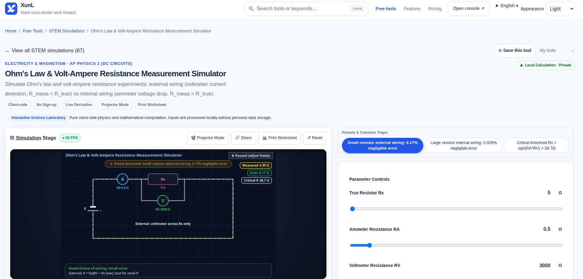
Follow-up: increase Rx while holding the meter resistances fixed. External wiring becomes more affected by voltmeter loading; the internal method’s fractional ammeter contribution becomes smaller. The page uses sqrt(RA×RV) as a wiring-selection threshold. Treat this as the familiar approximate comparison: the exact external relative error uses Rx/(Rx+RV), whereas the internal error uses RA/Rx. Do not confuse a selection shortcut with a meter calibration certificate.
Write down: “The external result reads low because the ammeter includes ___; the internal result reads high because the voltmeter includes ___.” This tests the cause, not recall of a preset name.
Investigation 2: a transformer changes voltage, not frequency
Open the ideal transformer simulator. Its documented model relates voltage, turns and current for a single-secondary ideal transformer:
U1/U2 = n1/n2
I1/I2 = n2/n1
Pin = Pout
- Select AC and record primary voltage, both turn counts and the resistive load. A documented setup to investigate is U1=220 V, n1=1100, n2=60 and load=12 Ω.
- Predict how the secondary voltage changes if only its turn count increases; compare the displayed voltage and currents.
- Hold the turn ratio fixed and change the load. Separate “what sets the voltage ratio” from “how much current the load draws”.
- Select the constant-DC preset. Ask whether magnetic flux is still changing in the steady-state model.
The expected steady-state DC secondary output is zero in this ideal induction model. Real switching transients are a different question, so “DC gives zero” is not a claim that switching a real coil never produces a voltage pulse. Do not reproduce this investigation with mains electricity.
On the Chinese page, Reset was followed by the preset “constant DC input, output is zero”: U1=220 V, n1=1100, n2=60, load=12 Ω, source type=constant DC. The live outputs were U2=0 V, I2=0 A, I1=0 A and transmitted power=0 W; the derivation states that steady DC has dΦ/dt=0. This records the simulator, not a safety claim about a real coil or a charger. AC voltage and current were not logged, so an ideal turns-ratio prediction is not quoted as a display reading.
The transmission-loss panel is another conditional model: for fixed transmitted power and line resistance, increasing transmission voltage lowers current, and resistive loss follows I²R. It does not model every loss in a power grid or make a charger efficient merely because it has more turns. The ordinary transformer does not change the AC frequency. For multiple secondary windings, use total power balance rather than applying one secondary-current ratio to all outputs.
Investigation 3: Lenz’s law opposes the change, not the magnet itself
In the Faraday and Lenz simulator, compare the N-pole approach and withdrawal presets while keeping turn count and speed comparable.
- Before running, mark whether the magnetic flux through the coil is increasing or decreasing.
- Predict the induced pole at the same coil face. On approach, the induced response opposes the increasing flux; on withdrawal, it opposes the decrease.
- Compare the displayed current direction from the same viewing side. Reversing your viewpoint also reverses the apparent clockwise direction.
- Change only speed, then compare the magnitude trend of the induced emf.
For a coil with identical flux through each turn, Faraday’s law gives emf = −N dΦ/dt; the minus sign expresses Lenz’s law. The page’s magnitude form N×ΔΦ/Δt needs that directional explanation. Opposing change does not mean preventing all change or creating energy. The mechanical work associated with the induction process matters.
In the Faraday/Lenz simulator, Reset was followed by the N-pole insert/approach preset: magnet speed v=1.5, facing pole=N, motion=insert/approach, coil turns N=100. The display showed induced emf=7.5 V (E=0.05×100×1.5=7.5 V), coil top pole=N, a repulsive force opposing the approach, and a counterclockwise induced current in the top view. A withdrawal comparison was not logged; do not reuse the approach polarity for a departing magnet. No open-ring control is assumed.
Motor connection: a short comparison, not another experiment suite
The DC motor and commutator lab offers with/without-commutator comparisons. Use it to distinguish two directions of energy conversion: a motor uses current and a magnetic field to produce torque; the induction example uses changing flux to produce emf. The commutator changes the coil-current direction at the appropriate rotor position in the model. An animated speed is not a motor performance curve or a safe stall-current specification.
Questions worth asking at the end
Does U/I make Ohm’s law universal? No. The simple constant-resistance model is for an ohmic resistor under controlled physical conditions. Diodes, motors and changing temperatures need more than a universal constant-R assumption.
Will a bridge or four-wire measurement eliminate every error? They address particular measurement problems, but no virtual comparison certifies a real instrument or guarantees zero uncertainty. This lab is the volt-ammeter arrangement, not a simulation of every precision method.
Can this replace a practical lab safety procedure? No. Keep these as virtual investigations; never infer a “safe voltage” for people from a classroom resistance model. The page’s client-side processing statement is not a network audit, and ordinary site resources may still load.
For the different engineering task of cable losses and sizing, see the voltage-drop guide. It is not the classroom simulator, and its job should not be confused with this measurement investigation.
Put this guide to work for your business
Start free tools with Google or an email code. Create a company and compare Pro plans when you need monitoring and team permissions.
Personal accounts use Free limits. A separate new company receives a 7-day Pro trial, excluding paid monthly credits.