The formula
Considering conductor resistance only (a common approximation for small and medium cables near unity power factor):
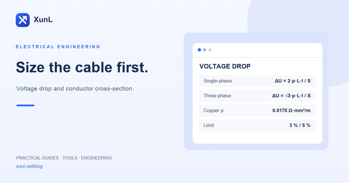
- Single-phase: ΔU = 2 × ρ × L × I ÷ S
- Three-phase: ΔU = √3 × ρ × L × I ÷ S
Where:
- ΔU: voltage drop (V)
- ρ: resistivity, about 0.0175 for copper and 0.028 for aluminum (Ω·mm²/m)
- L: one-way cable length (m); the 2 in the single-phase formula covers both conductors
- I: load current (A)
- S: conductor cross-section (mm²)
Voltage drop in percent = ΔU ÷ nominal voltage × 100%.
Working back to cable size
Rearrange for the allowed drop:
S ≥ k × ρ × L × I ÷ ΔU allowed (k = 2 single-phase, k = √3 ≈ 1.732 three-phase)
Round up to the next standard size: 1.5, 2.5, 4, 6, 10, 16, 25, 35, 50, 70, 95 mm² and so on.
Worked example: 380 V three-phase, 30 A, 80 m
Allowed drop 3%: ΔU allowed = 380 × 3% = 11.4 V
S ≥ 1.732 × 0.0175 × 80 × 30 ÷ 11.4 ≈ 6.38 mm²
6 mm² is too small, so choose 10 mm². Check: ΔU = 1.732 × 0.0175 × 80 × 30 ÷ 10 ≈ 7.3 V, about 1.9%.
The voltage drop and wire size calculator does this for copper or aluminum, single- or three-phase, and converts to AWG.
How much drop is acceptable
IEC 60364-5-52 Annex G (Table G.52.1) gives maximum drops from the origin of the installation to any load point:
| Supply | Lighting | Other uses |
|---|---|---|
| Directly from a public LV network | 3% | 5% |
| From a private LV supply (own transformer) | 6% | 8% |
These apply in normal steady-state operation, not during motor starting. National codes differ in values and where the measurement starts, so follow the rules for your project's location.
Voltage drop is not the whole check
- Current-carrying capacity: the cable must also be rated for the current under its installation method, ambient temperature and grouping.
- Reactance and power factor: for large cables, long feeders or motor loads use the full formula ΔU = √3 × I × L × (R cosφ + X sinφ); resistance alone underestimates the drop.
- Motor starting: direct-on-line starting current is several times the rated current, so the momentary drop is much larger. Estimate motor power and current with the motor sizing calculator.
- Temperature: resistance rises with conductor temperature; 0.0175 is a common engineering value, so correct for operating temperature in demanding cases.
Source
Tools for your next step
Put this guide to work for your business
Create a company account to try website monitoring and the inquiry workbench. Compare Pro plans for your team’s ongoing needs.
No card required. The trial returns to Free when it ends. Paid monthly credits are not included in the trial.